Original Article by Dan Kay
There is an important guideline about brazing filler metals (BFMs) that needs to be followed when performing any kind of brazing — namely, it is very important to feed brazing filler metal (BFM) into only one side of the joint to be brazed, allow that molten BFM to be pulled completely through the joint by capillary action until the BFM is visible at the other side of the joint, and can be seen to produce a complete braze-fillet (meniscus) around (or along) that opposite end of the joint.
As shown in Fig. 1, a BFM wire is being hand-fed into one end of a joint being brazed (gap is shown much thicker than desired only for illustration purposes), and the BFM flows all the way to the other side of that joint where it can be inspected for complete pull-through. This is an example of proper brazing in which “you feed from one side, and inspect on the other”.
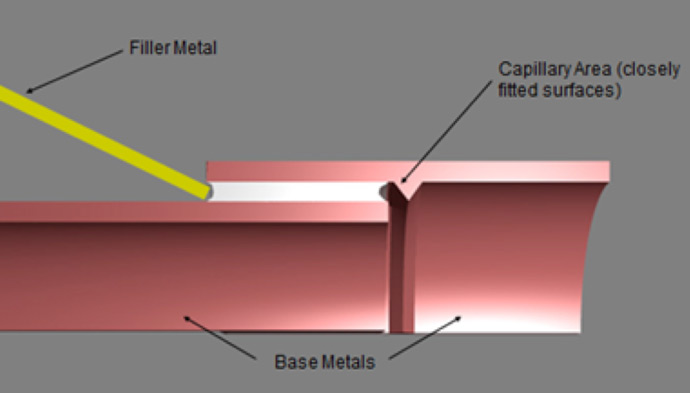
Fig. 1 Illustration of feeding BFM from one side of the joint and allowing capillary action to pull the molten BFM through the joint to the other side where it can be inspected. Drawing courtesy of JWHarris (Div. of Lincoln Electric).
It is never wise to feed BFM from both sides of the joint, since by so doing you can trap air, moisture bubbles, outgassing materials, etc., inside the joint between the two incoming walls of molten BFM, thus greatly increasing the void content in that joint. Fig. 2 shows an example of a cross-section photo of a round electrical contact that was brazed onto a flat surface, where the BFM was applied completely around the disc-shaped part that was to be brazed to the substrate below it. When the BFM melted and tried to flow into the joint, it could not do so since the air and other contaminants inside the joint could not escape to the outside since the “wall of liquid BFM” was blocking it. Thus, only a fillet formed around the outside of the joint but did not flow into the joint, as shown in that photo in Fig. 2.
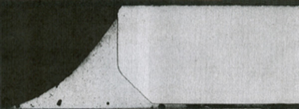
Fig. 2 The BFM around the disc melted in place, but could not effectively flow into the inside of the joint since the entrapped air could not escape.
This type of situation can be effectively prevented if the ring of applied BFM is only partial, such as that shown in Fig. 3, where the BFM paste (or solid preform ring) is applied only a little more than halfway around the OD of the part being brazed to the substrate. By so doing, as the BFM melts and flows into the joint, it will push any air, flux, or other gaseous contaminants out of the joint ahead of it as it moves in the joint and replaces that flux, air, gaseous contaminants, etc.
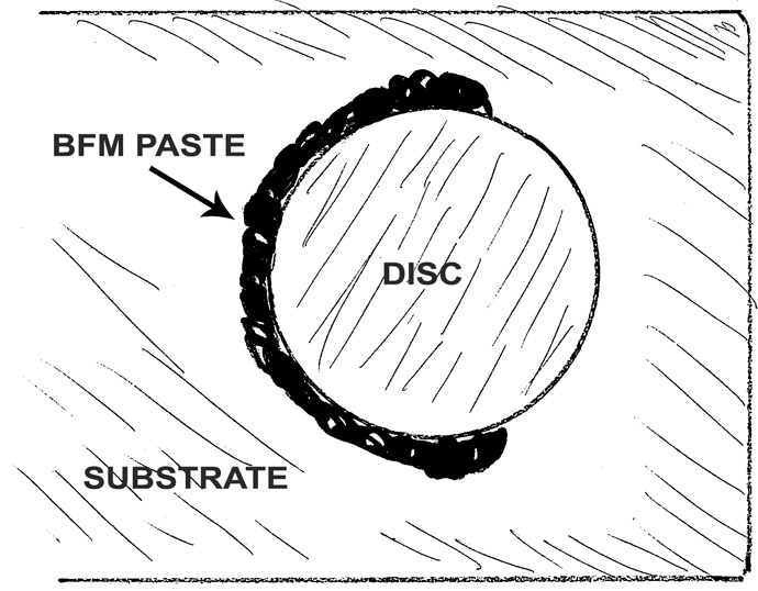
Fig. 3 A disc being brazed to a substrate below it, in which the applied BFM only goes a little more than halfway around the disc.
Learn to trust capillary action. This rule of applying from one side and inspecting on the other obviously depends on capillary action being able to effectively do its job when the BFM becomes molten and wants to flow. As we’ve discussed many times in other articles, good capillary action will depend on having proper gap clearance, clean surfaces inside the joint, and proper heating of the joint.
It also depends on your applying the correct amount of BFM to be able to fill the entire joint, and on the ability of the molten BFM to flow through the entire joint.
Take a look at the drawing in Fig. 4, which is a cross-section of an actual aluminum tube-in-fitting that was furnace brazed.
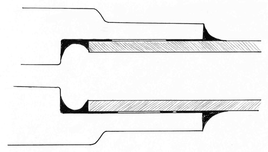
Fig. 4 A long aluminum tube furnace-brazed into an aluminum fitting. Notice the fillets at each end of the joint. How did they get there?
The drawing is an exact duplicate of the photo from which it was taken. Notice that there is good BFM filleting at each end of the joint, but significant non-brazed surfaces between those two fillets. Remember again that this is aluminum. I show this illustration in each of my brazing-training classes, and ask the attendees: “How did that BFM get from the right-hand side of the joint where the BFM was applied, all the way down to the other side of that long joint so as to form a nice fillet down at that end, too?” It’s a trick question. Aluminum BFM can only be realistically expected to flow a short distance into the joint (about 1-3T, where T is the thickness of the thinner member) because the temp required for aluminum brazing is literally within a few degrees of the melting temp of the base metals being joined. Thus, the molten BFM and aluminum base metal have a strong driving force to alloy with each other right now, rather than merely allowing the molten BFM to flow long distances along the aluminum tube’s surface without wanting to readily alloy into those surfaces instead. So then, how did the BFM get to the far end of the tubular joint? Obviously it had to be placed there from the start, thus having BFM applied to each end of the joint since the strong alloying-interaction between the molten BFM and the aluminum base metal could never have allowed so great a volume of molten BFM to flow such a long distance.
At which end of the joint should the BFM be placed? Since you should feed from one end and inspect on the other, I recommend that you try to place the BFM such that when it flows to the other side of the joint, that side to which it flows should be easy to inspect. Thus, it makes sense to place a preform inside a part, and allow the BFM to flow to the outside where it can be easily inspected (as shown in Fig. 5).
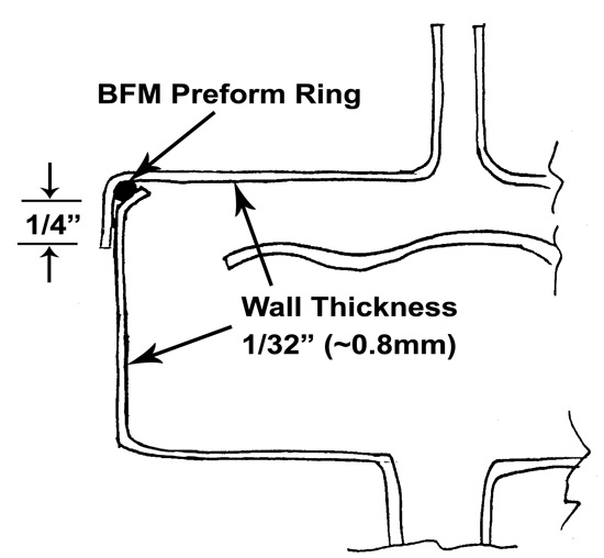
Fig. 5 A solid preform ring of BFM can be placed inside the part on a shoulder, as shown, so that when it melts and flows, it can be easily inspected from the outside of the assembly.
This can become a strong case for the use of solid preforms since if the BFM is placed inside a part, there should be no component of the BFM that would gas-off when heated. Thus, were BFM-paste to be used, the binders in that paste would volatilize into huge amounts of gas inside the part, possibly distorting the fit-up of the parts, or worse. When BFM is placed inside a component for brazing, I strongly recommend that it be solid material, which, when it melts, merely becomes a liquid that can flow by capillary action throughout the joint and then be easily inspected from the outside of the joint.
What about clad sheet? Many aluminum base-metals already have a cladding of BFM applied to their surfaces during original production in the mill. Therefore the BFM is already in place inside the joint, and the rule of “Apply from one side and inspect on the other” does not apply. Clad materials also have the advantage that they are solid coatings, and therefore outgassing of BFM components should not be a problem.
© Copyright Dan Kay 2020